Aorta: the design log
Document Rev AB — schematic and design signed off 2026-09-24. First article (Rev 1) to be built as a single hand-soldered test bed; Rev 2 follows once the kinks are out.
This is the documentary version — the thinking behind the decisions, not every micro-revision. And it's a living document: it gets updated as the work progresses — Rev 1 bring-up, whatever the test bed teaches us, the Rev 2 spin, and everything after. You're reading the current chapter, not the finished book.
Why Aorta exists
Bobby's build sequence was decided with one principle: Block 1 is the foundation — "solid internal organs." Before the head, before the chassis jewelry, the droid needs a power and interconnect backbone it can trust. Aorta is that backbone: a single 240 × 170 mm board that takes raw 3S battery power in one end and hands every subsystem exactly what it needs — fused, labeled, and serviceable.
It sits between the Arduino Ventuno Q (the brain, riding on standoffs above the board) and everything else: four drive motors via a Cytron MDD10A driver, pan/tilt and ear servos, IR and cliff sensors, WS2812B LED strips, a status panel, and an exciter-audio amplifier. Power distribution, signal routing, and fusing — all in one place, all visible, no rat's nest.
The name fits the job. The aorta is the one artery everything else branches from.
The power tree and the copper rules
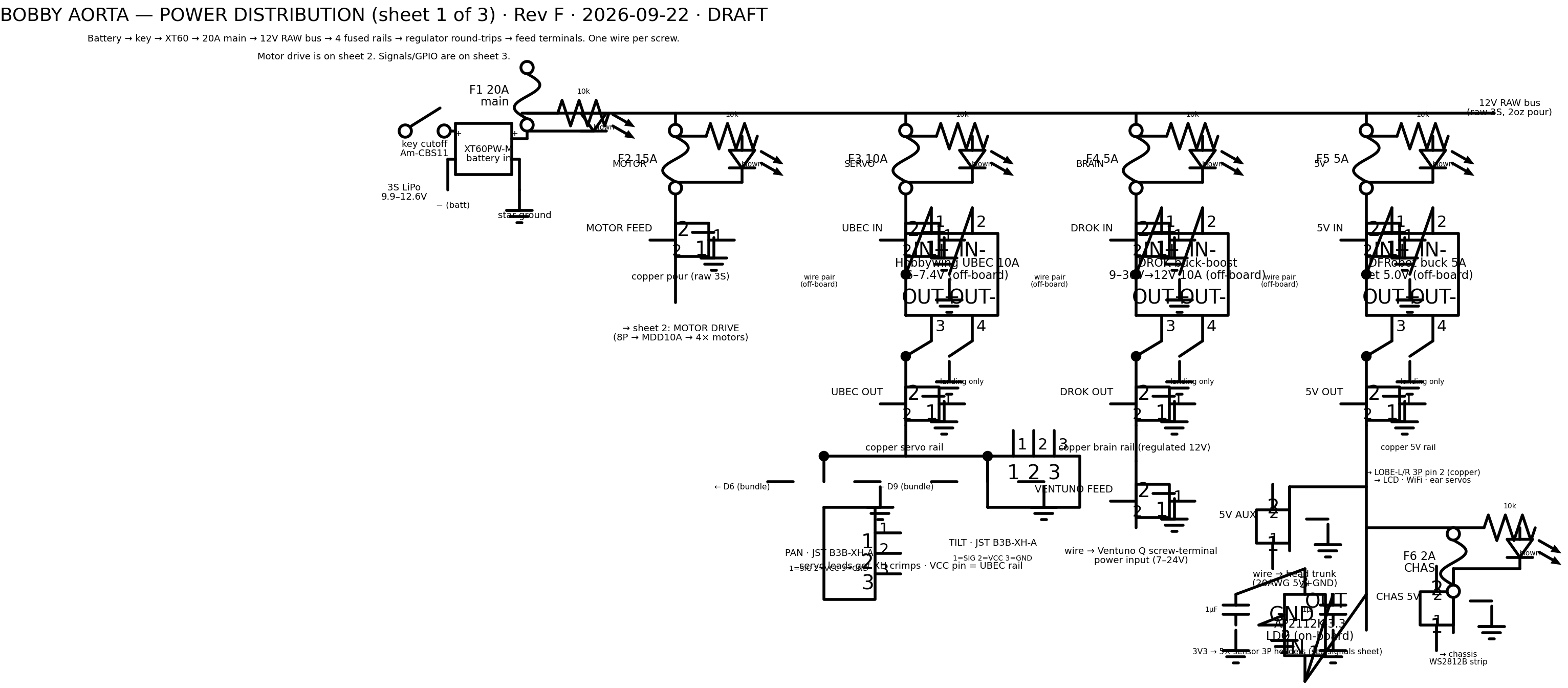
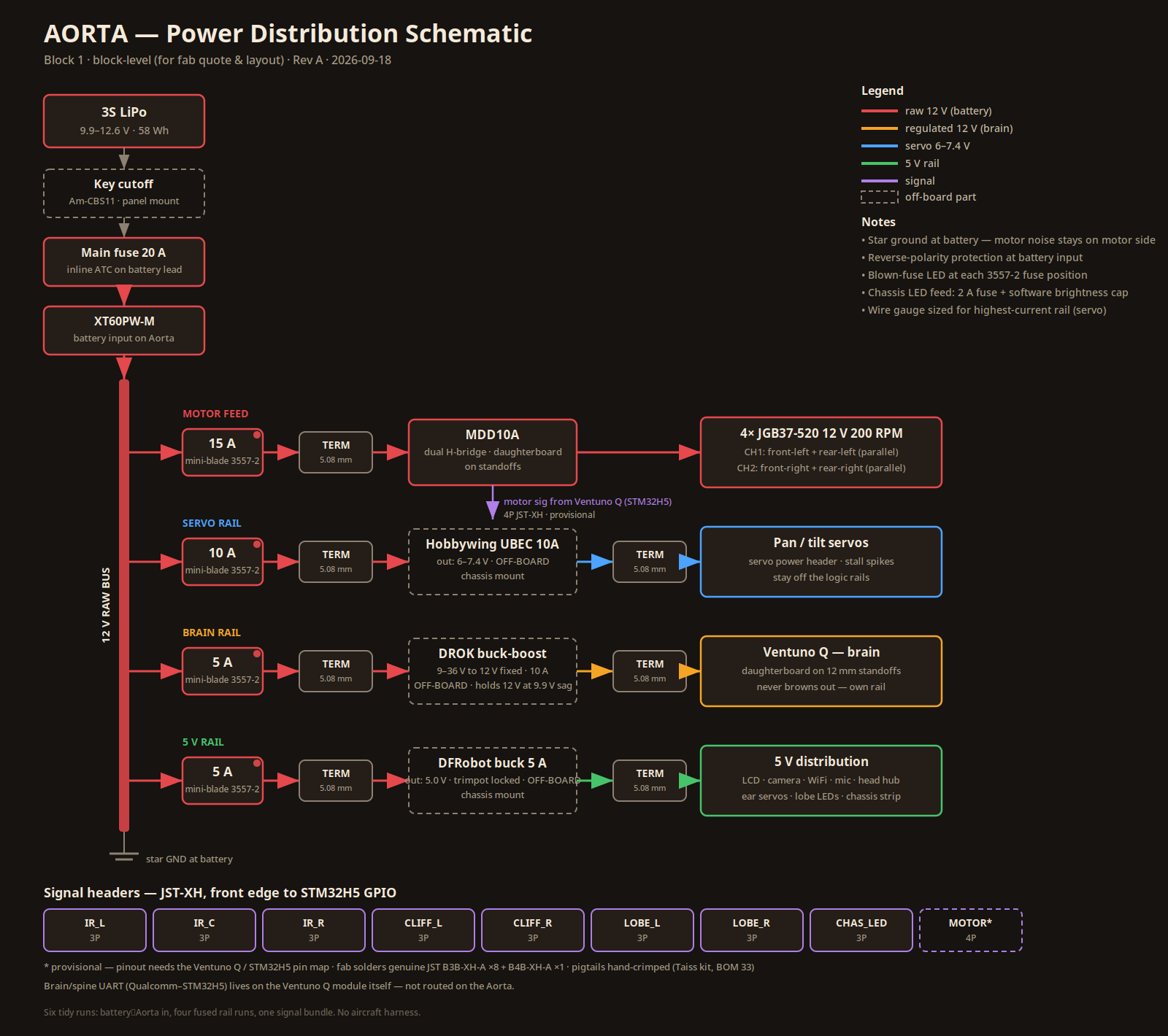
The first thing locked was the power tree — the read-this-first map of every rail. Its shape never changed after that first week, which is how you know it was right:
POWER TREE
| Battery in | Missile cutoff switch → 20 A inline MAIN fuse → XT60 → 12 V RAW bus. The MAIN is the single allowed inline fuse in the whole build. |
| Motors | Raw 3S straight to the MDD10A driver, 15 A fuse. The regulated 12 V rail is brain-side only — motor stall current browning out the brain is how robots do embarrassing things in public. |
| Brain | DROK 12 V → Ventuno only (5 A fuse) |
| Servos | Hobbywing UBEC → servo rail (10 A fuse) |
| 5 V | DFRobot 5 A buck → 5 V rail (5 A fuse) |
| 3.3 V | AP2112K-3.3 LDO → sensors, fed from 5 V, under 50 mA total, self-protecting, no extra fuse |
The copper rules were set the same week and held for the same reason — current is honest, and copper doesn't negotiate:
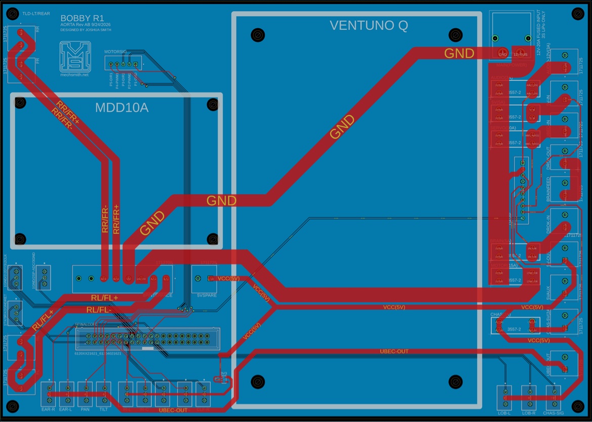
2 oz copper, high-current pours minimum 4 mm, preferably 6 mm. At the XT60 ground pins there wasn't room for 6 mm, so a 5 mm trace with a 5 mm choke on the pour at pin 4. The math checked: ~14°C rise at a full 15 A on 2 oz, comfortably under the 20°C budget. No thermal relief on high-current pads — spokes are resistance, and resistance is heat where you can least afford it. Thermal relief stays on the logic ground pour, deliberately: a solid pour is a giant heatsink, and without spokes the joints go cold and refuse to solder, especially by hand. Star ground at the XT60 (−) slot — motor noise stays on the motor side.
Buy the good stuff
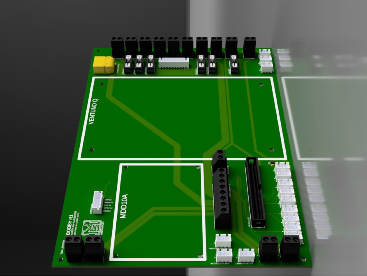
Phoenix Contact terminal blocks, not the cheap ones. "The cheap ones fail hard." Fifteen MKDS 3/2-5,08 two-position blocks plus one eight-position MKDS 3/8-5,08 for the MDD10A interface. When 15 amps flows through a screw terminal for years, the contact metallurgy is the whole game. This decision echoed all the way to manufacturing.
Genuine JST-XH through-hole board headers. Through-hole, not SMT, because connectors get plugged and unplugged and vibrated — through-hole survives that. Fifteen B3B-XH-A, one B5B-XH-A, one B10B-XH-A. Genuine JST pitch is 2.50 mm, not 2.54 — picked before fab, no clone footprints.
One wire per screw. A catch that reshaped the layout: regulator outputs land on dedicated 2P terminals and continue in copper to separate feed terminals. Loads never share a regulator's screws. It costs a few extra terminals and saves every future debugging session.
The 40-pin spinal cord and the split rails
The Ventuno-to-Aorta connection went through one clean kill: the planned 14-pin JST bundle was retired in favor of a full-GPIO 40-conductor ribbon. The Aorta landing is a Würth shrouded box header — keyed, through-hole, impossible to plug in backwards. Twenty-four positions carry every GPIO plus grounds; signals and ground only, no power in the bundle — power stays on the fused architecture where it belongs. Positions 25–40 are deliberately left with no copper, reserved for Rev 2.
The same stretch locked the split VCC rails: the 3P headers are not one rail. WS2812B LED headers get 5 V; IR and cliff sensor headers get 3.3 V from the on-board LDO — because those sensor outputs track VCC, and 3.3 V logic goes straight into the Ventuno GPIO with no level shifting. One LDO, five sensors, zero extra parts.
Then the servos: board-mounted JST for pan/tilt, plus two dedicated ear-servo headers, EAR-L and EAR-R. Bobby definitely needs ears.
The status panel got its heartbeat: an amber LED driven from Ventuno A0 blinking at ~1 Hz — blinking means the brain is alive, not just the power rail — plus a 2-wire LED voltmeter across the RAW bus (12.6 full, ~11.1 nominal, 9.9 land-now). And when the question came up whether the fuse LEDs should be lit-when-good, the answer was no: red means fault, and a dark panel is the fastest healthy read you'll ever get.
Two late additions rounded out the design: a dedicated AUDIO rail — 3 A fuse on the RAW bus feeding the exciter amp — and the missile-switch master cutoff: a sealed toggle with a red flip-up aircraft guard, replacing the key switch. One-handed emergency cutoff, no key to lose, and the guard holds it OFF when closed.
The schematic audit: what it caught
The full section-by-section audit passed — and earned its keep on four catches:
1. QAMP pin 4 → GND. The design doc already had it right; the schematic didn't. Fixed in the schematic, confirmed present in copper.
2. The MOTORSIG mirrored pinout. Checking the actual Cytron MDD10A user manual revealed the old 5P pin order would have put DIR1 straight to ground through a straight harness. Corrected order mirrors the driver's real header. This is the catch that pays for every audit.
3. B3B-XH-A count reconciled 12 → 15 — twelve device headers plus three spare/debug. The 2P terminal count re-checked and finalized at 15.
4. 40P positions 25–40 confirmed unconnected at schematic level; the remaining rule is layout-only: no copper on those pads.
The manufacturing arc
With Rev AB signed off, the question was how to get copper in hand. Two JLCPCB quotes were explored: bare PCBs came to $72.30 + $29.69 DHL; the full-assembly cart showed $161.53 for five assembled boards — which turned out to need a correction: the $161.53 is the service line (PCB + labor + fees) and does not include the $109.05 in parts. Real assembly math: ≈ $340.
Then the engineering friends weighed in: with JLCPCB assembly, you don't always get the parts you specced — substitute components are a known risk. On a board whose entire design philosophy is "buy the good stuff" (genuine Phoenix blocks carrying 15 A), that warning landed hard. Decision: bare boards from JLCPCB, every part self-sourced from DigiKey/Mouser, even if it costs more.
The twist: it doesn't cost more. The DigiKey/Mouser price check (genuine parts, no substitutes) came back at ~$205 for five boards' worth of parts — and skipping JLCPCB's assembly labor and fees more than offsets the genuine-parts premium. Bare boards + genuine parts ≈ $305 vs. ≈ $340 for JLCPCB assembly — about $35 cheaper and every part is the real manufacturer component.
And since JLCPCB's minimums are 5 bare / 2 assembled anyway, the plan wrote itself: Rev 1 is a single hand-soldered test bed. Five bare PCBs plus one board's parts (~$45 from DigiKey) ≈ $145 for the first working board, with four spare bare PCBs banked. Prove the footprints, prove the QAMP fix in real copper, find the small kinks — then Rev 2 is rock solid.
Next: build the Rev 1 test bed
What's left to confirm before ordering: the 40P no-copper check at layout level, the XT60 footprint locked against the physical sample, and the audio signal interface — power side done, signal path still open, do not order around it. JLCPCB closures run Sep 25, Sep 27, Oct 1–4 — order early.
This log will keep growing: Rev 1 bring-up, the test-bed lessons, the Rev 2 spin. Check back.
← Back to the build log